Journal of Multidisciplinary Dental Research
DOI: 10.38138/JMDR/v5i1.9
Volume: 5, Issue: 1, Pages: 49-55
Case Report
Fouziya Begum1, Uthappa M A2, Basavaraj S Salagundi3, Rupesh P L4, Bharat Kataraki5, Sharon Abraham6
1Postgraduate student Coorg Institute of Dental Sciences, Virajpet
2Reader, Coorg Institute of Dental Sciences, Virajpet
3Professor and HOD, Coorg Institute of Dental Sciences, Virajpet
4Professor and Chair, Coorg Institute of Dental Sciences, Virajpet
5Senior Lecturer, Coorg Institute of Dental Sciences, Virajpet
6Former Postgraduate student, Coorg Institute of Dental Sciences, Virajpet
Corresponding author:
Basavaraj S
Professor and HOD Dept of Prosthodontics
Coorg Institute of Dental Sciences Virajpet Karnataka
Email: [email protected]
Received Date:05 April 2019, Accepted Date:25 May 2019, Published Date:10 June 2019
In the existing practice of fixed prosthodontics, certain situations like pier abutments, tilted abutments create problems with rigid connectors. If rigid connectors are used in this situation, the pier abutment will act as a fulcrum because of physiologic tooth movement, arch position of the abutment, and the retentive capacity of the retainers. A nonrigid connector may be preferred in construction of fixed partial denture (FPD) with pier abutment. In this prosthesis, the movement of the nonrigid connector is enough to prevent the pier abutment from serving as a fulcrum. This clinical report describes rehabilitation of a patient with FPD with pier abutment using semi-precision attachment. The technique used is simple, economical, and feasible in a simple laboratory set up.
Key words: Precision attachment, Nonrigid connector, FPD
The preferred method for the fabrication of most of the fixed partial dentures is the use of rigid connectors (solder joints) between the pontic and retainer.
In the presence of pier abutments, a rigid connector is not indicated due to:-
In long span prosthesis these movements create stresses on the abutment. There should be some means which can neutralize these forces. Non- rigid connectors are indicated in such cases.
An non-rigid connector acts as an stress breaking mechanical union of retainer and pontic which is used in the form of a key (tenon) which will be attached to the pontic and a key-way (mortise) which will be placed within the retainer.
Non-rigid connectors in fixed prosthodontics are usually indicated in :-
Different types of non-rigid connectors are:
Case Report
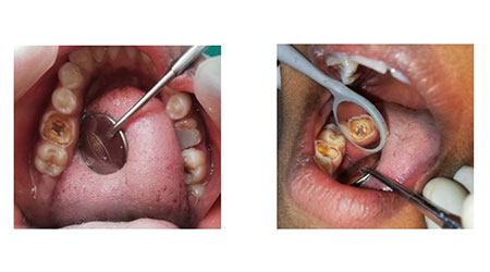
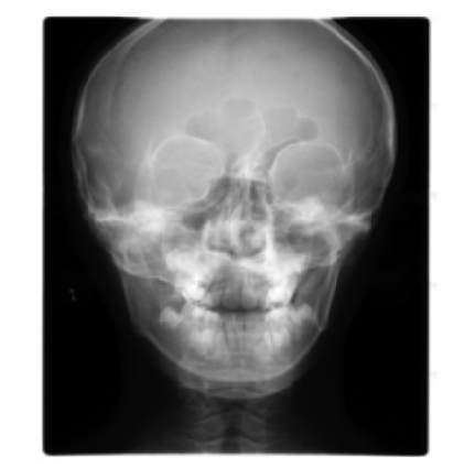
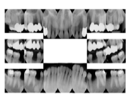
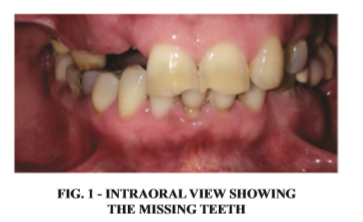
A 56 year old female patient reported to the department of prosthodontics at Coorg Institute of Dental Sciences with missing teeth #13, #14,# 17 and #14 , #16 [fig 1]. She also complained of difficulty in chewing and esthetics. Radiologically and clinically, the abutment teeth were having favorable criteria.
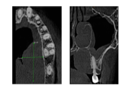
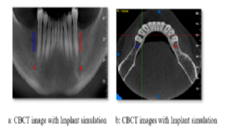
Evaluating all the treatment options , their pros and cons it was decided to rehabilitate the case with an five unit FDP using non-rigid connectors on the distal aspect of pier abutment. The other treatment options which were given to this patient were “tooth supported over denture, to extract all the teeth and give a conventional complete denture, root mimetic approach, placing two implants one in each edentulous regions followed by independent crowns. This treatment option was decided to completely eliminate the load and fulcrum-like situation associated with the pier abutment. Implants can only be placed after complete medical and radiological evaluation. In cases where implants cannot be placed because of medical or financial conditions nonrigid connectors are advocated.
This treatment with a semi precision attachment
was opted because non rigid connector transfers shear stresses to supporting bone rather than concentrating them in connectors. It also tends to minimize the mesiodistal torquing of abutments and allowing them to move independently. The design of complex fixed partial dentures when segmented into shorter components makes it easier to change.
Step-by-step procedure:
Diagnostic casts were made The tooth preparation of # 21, #11, #12, #15, #17 was done
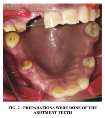
first followed by #21, #23, #25, #27 was done for metal-ceramic FPD and nonrigid connector between the #15, #16 and #25, #26 was given. The procedure was done step by step, after the completion of one arch the other side treatment was started.
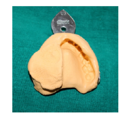
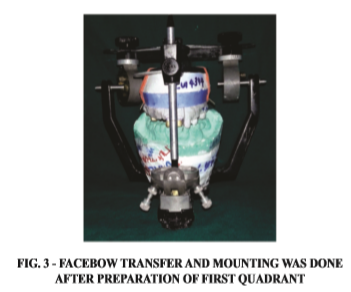
Putty-wash impression (3M ESPE, USA) was made for the preparation of the working model. It was poured in high-strength die stone (Kalrock Pvt Ltd, India). Polyether material (Ramitec, 3M ESPE, USA) was used to make interocclusal records. Followed by provisional restoration and die preparation was done. Cast was mounted on articulator with face bow transfer and was programmed using interocclusal records for the first quadrant [fig 3] followed by the second quadrant.
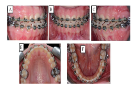
Wax pattern fabrication was done and recess for the female was cut accordingly to fit the plastic tenon on distal aspect of pier abutment. Tenon was lubricated with petroleum jelly and then wax-up was completed for exact fit. Accurate alignment of mortise is important as it must be parallel to path of placement of distal retainer. An dental surveyor (Williams Surveyor, Williams Dental Supply Co., Worcester, MA) is used to accomplish it. Try-in of the individual units were done to check proper
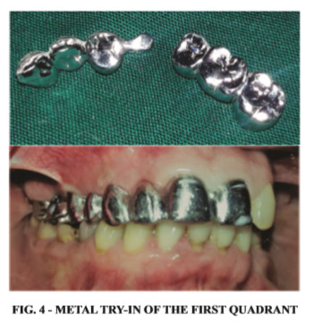
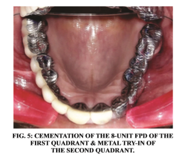
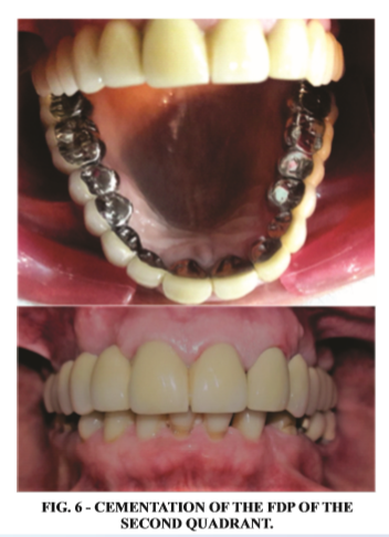
seating. Ceramic facing was then proceeded [Figure 4 & 5]. followed by the second quadrant [Figures 6].
Discussion
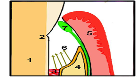
When rigid connectors are used in presence of an pier abutment, an occlusal load applied on the
abutment tooth at one end of an FDP (mainly the molar retainer) with a pier abutment, the pier act as a fulcrum. Tensile forces will then be released between retainer and the abutment at the other end of the restoration (premolar retainer). Extrusive force will be experienced by the anterior as well as posterior abutments and the resultant tensile force at the retainer to abutment interface leads to loss of retention of these restorations resulting in marginal leakage, caries of the abutment and FDP failure. Hence non-rigid connectors are recommended in such clinical situations.
Carl E Misch9 proposed that in conventional fixed prostheses, the “male” portion of a nonrigid attachment usually is located on the mesial aspect of the posterior pontic; whereas, the “female” portion is in the distal aspect of the natural pier abutment tooth there by preventing mesial drift from unseating the attachment.
Mesial drifting doesn't happen in case of an implant placement aswell as non-rigid connector location is more flexible. Stress breakers are not indicated when two implants are placed between the natural pier abutments. Shillingburg10 published proposed the connector to be placed at the distal aspect of pier abutment.
Posterior teeth long axis tends to tilt mesially, occlusal forces applied vertically produce further movement in this direction. This would eliminate the fulcrum effect and the patrix/male of the attachment will be seated firmly in place when pressure being applied distally to the pier. Non-rigid connectors are contraindicated in certain situations like:-
Designs of the nonrigid connectors are key & keyway (Tenon- Mortise), cross – pin & wing, loop and split connectors. The most commonly used design is mortise (female component) placed within the contours of the retainers and a Tenon (male 14component) attached to the pontic. Positioning of the dove tail or cylindrically shaped mortise is important as it must be parallel to the path of withdrawal.
ADVANTAGES OF TENNON MORTISE DESIGN ARE :
DISADVANTAGES :
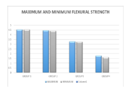
The size, shape, and type of connector assess the success of an FPD. Biomechanical features such as overload, leverage, torque and flexing can lead to abnormal stress concentration in FPD. When stress distribution of different design types were compared, high stress values were shown at the connectors and cervical regions of the abutment teeth near the region of the pier abutment. Other stress concentration areas were apical aspects and root surfaces. These factors play a vital role in potential for failure in long span FPD.
When a rigidly designed FPD with pier abutment is being used, it will act as a lever, high stress concentrations will result at the pier abutment and excessive displacements may be observed at the terminal abutments, leading to damage to the abutment teeth. Thus non-rigid connectors are indicated to use to eliminate the fulcrum action of the abutment teeth. Non-rigid connector helps in transferring shear stresses to supporting bone rather than concentrating at the connectors.
It reduces the mesiodistal torquing of the abutments and helps them to move independently. Segmenting an complex fixed partial denture into shorter components makes it easier to replace individually. Moulding et al performed an photoelastic stress analysis of supporting alveolar bone as modified by nonrigid connectors.
The authors evaluated that there will be a change of stress fields depending on the location of nonrigid connectors. When a non-rigid connector is incorporated at the distal region of the pier abutment, the amount of stress concentration in the pier abutment will be reduced. There won't be any stress concentration at the anterior abutment with posterior loading and viceversa with this type of design.
This clinical case report discusses the use of an non rigid semi-precision type of connector between distal of 25 and mesial of 26 pontic and 15 and 16 pontic, where 25 and 15 act as a pier abutment. There is a difference in opinion on where to place the non-rigid connector incase of pier abutment. Markley[1] suggested placement of the non-rigid connector on one of the terminal abutments and not on the pier abutment.
Adams[2] suggested placing the connector at the distal side of pier, if required, adding one more at the distal side of the anterior retainer, while Gill[3] suggested placing it at one side or both sides of the pier . Shillingberg[4] suggested placing the connector on the distal aspect of pier abutment. Since the long axis of the posterior teeth tends to lean in a mesial direction, vertically applied occlusal forces produce more movement in this direction.
This would eliminate the fulcrum effect and the patrix of the attachment will be seated firmly in place when pressure being applied distally to the pier. This position have been justified by finite element analysis study[5] done by Oruc et al. In this case, we have placed it on distal aspect of the pier.
Conclusion
Subscribe now for latest articles, news.