Journal of Multidisciplinary Dental Research
DOI: 10.38138/JMDR/v5i1.2
Volume: 5, Issue: 1, Pages: 12-18
Original Article
Yasushi Yamazaki1, Takumi Ogawa2, Yuko Shigeta2, Tomoko Ikawa2, Noriyasu Hosoya2
1Dept. of Endodontology, Tsurumi University School of Dental Medicine, Yokohama, Japan.
2Dept. of Fixed Prosthodontics, Tsurumi University School of Dental Medicine, Yokohama, Japan.
Corresponding author:
Yasushi Yamazaki
Associate Professor Department of Endodontics
Tsurumi University School of Dental Medicine, Yokohama, Japan.
Email: [email protected]
Received Date:15 January 2019, Accepted Date:28 February 2019, Published Date:15 March 2019
We developed a dental fiberscope that can be navigated. As a result we are able to better grasp the device position relative to the teeth, aiming at the lesion more precisely. However, some level of distortion was present, and became more pronounced with wide-angle lenses. Furthermore, the device position and the precise target setting were difficult to consistently ascertain. The aim of this study is to navigate the tip position of the dental fiberscope in the root canal and to improve the navigation system accuracy.
We created a dental fiberscope with channels for laser and flooding. A 3D tooth model was made from the raw dental CT data. CT data was imported to image analysis software and segmented based on the CT value. In addition, the optical position of the measurement device, OPTOTRAK system, was used for registration of the 3D model, the actual teeth position, and to chase the scope movement. We developed exclusive software to unify information. The optical distortion in the endoscopic image was numerically rendered to the CT image.
We were able to precisely indicate the device position relative to the teeth on the 3D model in the monitor. This allowed us to aim at the lesion more precisely, as the revised endoscopic image matched the 3D model. Consequently, we were more able to grasp the correct position of the endoscope, allowing us to perform laser irradiation on the lesion with a higher degree of safety and precision.
Keywords: Fiberscope, Navigation system, Endodontic treatment
In the field of endodontic treatment, advances in dental CT scanning have contributed to progress in imaging procedures, three dimensional scanning of root canal direction, and improvement in the rate of detection of lateral branches. Among dental treatments, however, root canal procedures performed without macroscopic observation of the anatomy of the affected parts require considerable skill.
The anatomy of the tooth makes root canal treatment difficult. Specifically, the root of the tooth is curved and branches are formed throughout the root canal.
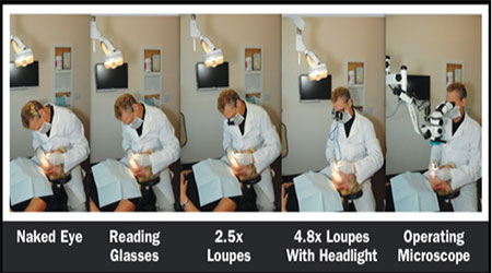
Recently, microscopes and dental fiberscopes (FS) have increasingly been employed for dental treatment. These devices have enabled examinations and treatments to be conducted using a magnified visual field or under bright vision and are indispensable in treating refractory dental problems.
In the field of general medicine, an endoscope is used to identify or treat lesions located in the intestine or abdominal cavity that cannot be observed directly, and the endoscopic procedure is reported to have high diagnostic accuracy. In the field of dentistry, a dental FS has recently been developed and applied to the observation and treatment of lesions in the periodontal tissues and for root canals.
The prototype dental FS has multipurpose channels that can be used for irrigation, special device insertion and laser irradiation. An operator can control the device while checking the distance between the device and the lesion on a monitor. Use of dental FS contributes to improvement in treatment precision. In the present study, using a dental FS incorporating multipurpose channels that allows laser fiber insertion, we identified the lesion and the position of the laser tip. In this manner, we were able to conduct laser irradiation efficiently while checking the contact of the laser tip with the lesion. Through this approach, we obtained satisfactory results in the basic research and clinical application of dental FS.
One challenge of using a dental FS is that the operator cannot obtain sufficient information about distance from the visualized image and it is difficult to figure out the positional relationship between the device and the lesion. To address this problem, we developed a dental FS navigation system for root canal endoscopy that enables real-time display of the dental FS tip position and the positional relationship between the tip and the tooth1), thus allowing the operator to easily understand their positional relationship.
This navigation system enables the correct targeting of lesions since the position of the dental FS tip and the positional relationship between the tip and the tooth are displayed in real time on the monitor and are thus easily assessed. In the case of clinical application of the root canal endoscopy navigation system, the accuracy of the system should be higher than that of a medical navigation system. Factors likely to affect the navigation system include errors in segmentation, positional information integration and the positional sensor, deviation of markers on three-dimensionally reconstructed images, and distortion of endoscopic images. Before clinical application of the dental FS navigation system, distortion of endoscopic images must be minimized to assure a higher level of treatment accuracy.
In the present study, efforts were made to improve these factors and develop a function to correct distorted images in real time. Satisfactory results were obtained from these efforts and are reported in this paper.
Methods
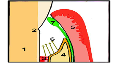
Fig.1 shows an overview of our navigation system for the dental fiberscope. The navigation system was created as follows.
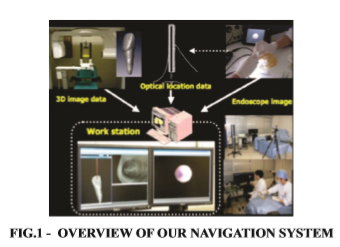
First, the fiberscope consists of image fibers (6,000 pixels, focus depth: 5 mm, field corner: 70 degrees) together with light guides and a working channels for other dental instruments and flooding. The outer diameter of the fiberscope needle is 1.1mm (Fig. 2).
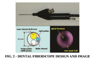
We observed the image through the dental fiberscope with a color video monitor using an imaging device.
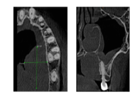
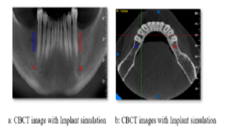
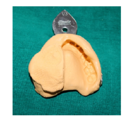
Second, the extracted natural tooth was implanted on the phantom and a CT was taken.
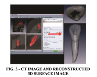
The image parameters were as follows; image size: 512*512, FOV: 180mm*180mm, pixel size: 0.351mm, slice thickness: 0.5mm. The three dimensional (3D) tooth model was made from the raw dental CT data. This CT data was imported to image analysis software and segmented based on the CT value. A 3D tooth model was made from the raw dental CT data (Fig. 3).
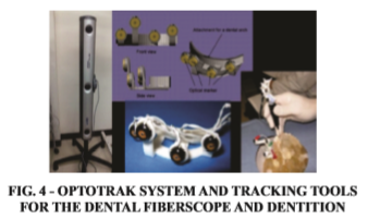
In addition, the optical position of the measurement device, OPTOTRAK system (NDI Inc., Canada), was used for registration of the 3D model, the actual teeth position, and to chase the scope movement. Fig.4 shows the tracking tools for the endoscope and dentition. And Fig.4 shows the attached these tools with the phantom. This tool was constructed by 4 markers of OPTORAK which was arranged 3D (not on the same plane).
We developed exclusive software to unify information. We were subsequently able to precisely indicate the relation of the position between the device and the teeth on the 3D model in the monitor.
The method of the image distortion has two steps. At first, camera parameter of the endoscope system was calculated by Open CV library (http://opencv.jp) which is useful for image analysis. The focal distance and the optical center point of the camera lens were estimated by this calculation. Black and white checker board, which is 3.0mm cells, was used in this step.
Second, input camera image was distorted correctly by using OpenGL Shading Language (GLSL). Specifically, input camera image stored the rectangle texture memory which size is the same as the input image. Next, the distortion correction texture coordinates were calculated by using the estimated camera parameter.
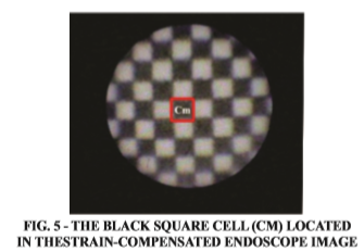
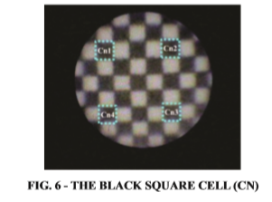
To validate the accuracy of our system, the distortion ratio was measured by using 0.3 mm black and white checker board. At first, the black square cell (Cm) size which is located in the center of the strain-compensated endoscope image, as shown in Fig.5. The size of Cm is the reference length. Then, the black square cell (Cn) was decided as shown in Fig.6.
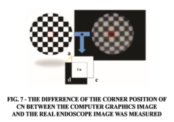
Next, the computer graphics image of the black white checker pattern, which consists of the size of Cm, was created by the image drawing software.
After that, the strain-compensated endoscope image was overlapped with the computer graphics image, as the origin Cm.
By using the overlapped image, the difference of the corner position of Cn between the computer graphics image and the real endoscope image was measured (Fig. 7).
The measurement for the ordinary endoscope image was experimented in the same method.
In this experiment, the endoscope was controlled by the mechanical device which equipped with the high performance and accuracy as shown Fig.8.
Results
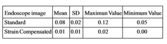
Fig.9a shows the result of the train-compensated endoscope image while Fig.9b shows the ordinary endoscope image. The result of the experiment was shown on Table.1. As the result of the ordinary endoscope image, the difference length was 0.12/0.052/0.076 (max/min/ave[mm]). On the other hand, the result was 0.024/ 0.003/ 0.0145 (max/min/ ave[mm]) for the strain-compensated endoscope image.
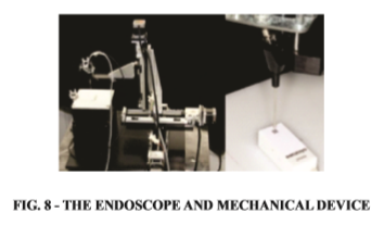
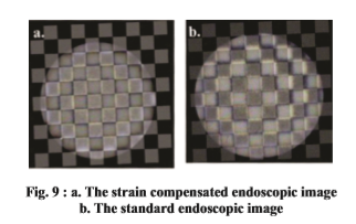
Table 1 The difference between length of the corner position of Cn between the computer graphics image and the real endoscope image (mm)
Discussion
We experimentally produced a dental FS that enabled irrigation of the root canal and periodontal pocket, insertion of a special device and laser irradiation. The device enables an operator to control it while checking the distance between the lesion and the device on a monitor. While dental FS successfully improves treatment precision, it is difficult for the operator to obtain sufficient information on distance from the image visualized by the dental FS, and it is difficult to determine the correct positioning of the device with respect to the lesion. To address this problem, we developed a dental FS navigation system that allows the operator to easily ascertain the position of the dental FS tip and the positional relationship between the tip and the tooth.
If we were grasp the correct position of the endoscope, we can safety and accurate laser irradiation to the lesion.
A phantom was fabricated by stereolithography and a human central incisor extracted from the upper jaw was implanted into it for observation. Cone beam CT PSR9000N for dentistry (ASAHI ROENTGEN IND., Japan) was used to obtain three-dimensional image information on the extracted tooth implanted phantom. By using image analysis software, the three-dimensional extracted tooth implanted phantom model was reconstructed from the CT data set. The dental FS CAD was produced by measuring the dental FS form with a three-dimensional profilometer. An optical position measurement device (OPTOTRAK, Northern Digital Inc., Canada) was used to obtain positional information on the tooth for observation and the dental FS CAD. The optical marker was fixed to the supporter of the dental FS, and the optical marker used for tracking dentition was fixed to the phantom model. Registration of the position of the optical marker was completed in the following manner: Three characteristic surface points were determined in the virtual space and the corresponding points on the real object were indicated by the reference point supporting tool. Image information was obtained while the tracking tools were fixed to both of them. Measurement accuracy was improved, and the three-dimensional reconstructed images of the phantom model and the endoscopy CAD and their positional information were obtained. In this manner, the navigation system was constructed in the virtual space.
By using the navigation system in the root canal, the position of the dental FS tip and the positional relationship between the tip and the tooth were able to be displayed in real time on the monitor. The form of the root canal fabricated as the threedimensionally reconstructed image was similar to that of the root canal displayed on the dental FS monitor. Synchronization in movement was also confirmed. The color and transparency of the tooth could be changed to create an image corresponding to the procedure selected by the operator. Thus, the operator could easily ascertain the stereoscopic positional relationship between the root canal and the dental FS. These adjustments enabled the operator to correctly target the lesion. We assigned the appropriate color or transparency to the each object. We could understand the relation of position between teeth and the device, and aim at the lesion precisely. Moreover, simultaneous display of volume data contributed to intuitive understanding of the presence of branches and the simple acquisition of detailed information. Consequently, the application of endoscopic navigation system could increase the success rate for root canal treatments with recalcitrant lesion.
However, in terms of the positional information based on the three-dimensionally reconstructed images on the monitor, a slight difference exists between the root canal and the dental FS tip. It will be necessary to correct the difference in the actual positional information between the root canal and the dental FS tip and improve accuracy to a level that can be accepted in a clinical setting.
Factors likely to affect the navigation system include errors in segmentation, positional information integration and the positional sensor, deviation of markers on the three-dimensionally reconstructed images and distortion of endoscopic images. In the present study, we developed software to correct distortion in the endoscopic images and succeeded in improving them. This result demonstrates that the degree of recognition of the form on the observation image can therefore be increased and a more accurate diagnosis made. Generally, endoscopes are used in the medical field to observe soft tissues. Because objects differ in their form, the necessity for correction of distortions in endoscopic images appears to be limited. In the field of dentistry, the objects are generally hard tissues, including teeth. Therefore, correction of distortion in endoscopic images is important for recognizing more precise form and may contribute markedly toward making precise diagnoses.
In the present study, we successfully corrected endoscopic image distortion. Attempting to establish a highly accurate navigation system requires examination of the overall accuracy of the system, while paying due consideration to various factors, including errors in positional information integration and the positional sensor, as well as marker deviation.
The present study suggested that a highly accurate navigation system could be established and used in a clinical setting after examining overall accuracy, including investigation of segmentation error.
Conclusion
We have developed the dental fiberscope navigation system. In this study, we were able to perform the reduction of the endoscope image distortion. Our experiment could validate that the accuracy of the surgical navigation was depended on the presence or absence of the image distortion.
As a result, the form of the lesion came to be recognizable more precisely and good operational views were obtained during the laser irradiation.
In addition, we were more able to grasp the correct position of the endoscope, allowing us to perform laser irradiation on the lesion with a higher degree of safety and precision.
Consequently, the improvement of dental fiberscope navigation system could increase the success rate for root canal treatments with recalcitrant lesion.
Subscribe now for latest articles, news.